Jack the Gripper: Blackjack Robot
University of Toronto — MIE438 Microcontrollers and Embedded Systems · April 2025
Garvish Bhutani, Alex Cho, Chaewon Lim, Maria Salonga
Abstract
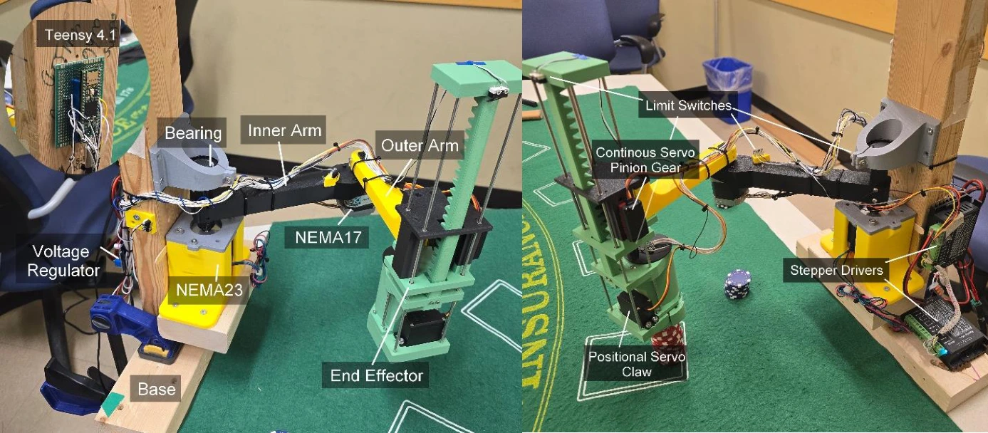
Jack the Gripper is a blackjack-themed pick-and-place robot built around a three-degree-of-freedom SCARA arm. A Teensy 4.1 coordinates two stepper-driven rotary joints, a servo-driven vertical axis, and a chip gripper. Through USB serial commands, the robot moves a requested number of poker chips between table positions and performs hit and stand gestures. The completed project focuses on embedded motion control and chip manipulation; the originally proposed camera-based card recognition and autonomous gameplay were scoped out after early testing.
Technologies
My Contribution
I led the inverse-kinematics system, translating desired end-effector positions into joint targets for the SCARA arm. I also worked on Teensy embedded integration, set up the servo motors, and contributed to the arm's vertical up-and-down mechanism.
Across the project, I helped brainstorm the design, plan the system, and work through integration decisions with the team. The mechanical, electrical, and control-system results below describe our combined work.
From Blackjack Concept to Working Manipulator
The original proposal combined card detection, gameplay decisions, and a robotic arm that could place bets and collect chips. The delivered prototype concentrated on the physical interaction: picking a chosen number of chips from a stack, moving them to another position, and gesturing to a dealer.
A move command supplies source coordinates, a chip count, and destination coordinates. The controller performs the pickup and placement sequence. A hit command taps the table twice; a stand command produces a side-to-side gesture. These actions are commanded by a user over USB serial rather than selected by an autonomous blackjack strategy.
Mechanical Design & Chip Gripper
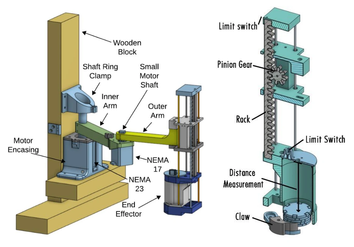
A NEMA-23 stepper at the base drives the inner arm, while a lighter NEMA-17 drives the outer arm. Together, the two joints position the end effector in the table plane. A rack-and-pinion mechanism driven by a continuous-rotation servo provides vertical motion; a separate positional servo closes the claw around the chips.
The assembly combines 3D-printed components, linear bearings, guide rods, and a wooden table mount. Testing exposed sag and heat-related softening of PLA near the outer-joint motor. Reprinting the inner arm and shaft adaptor in ABS, tightening the shaft connection, and replacing the original vertical servo with a stronger model improved the mechanism. The gripper was tested lifting a stack of 20 chips.
Electronics & Embedded Integration
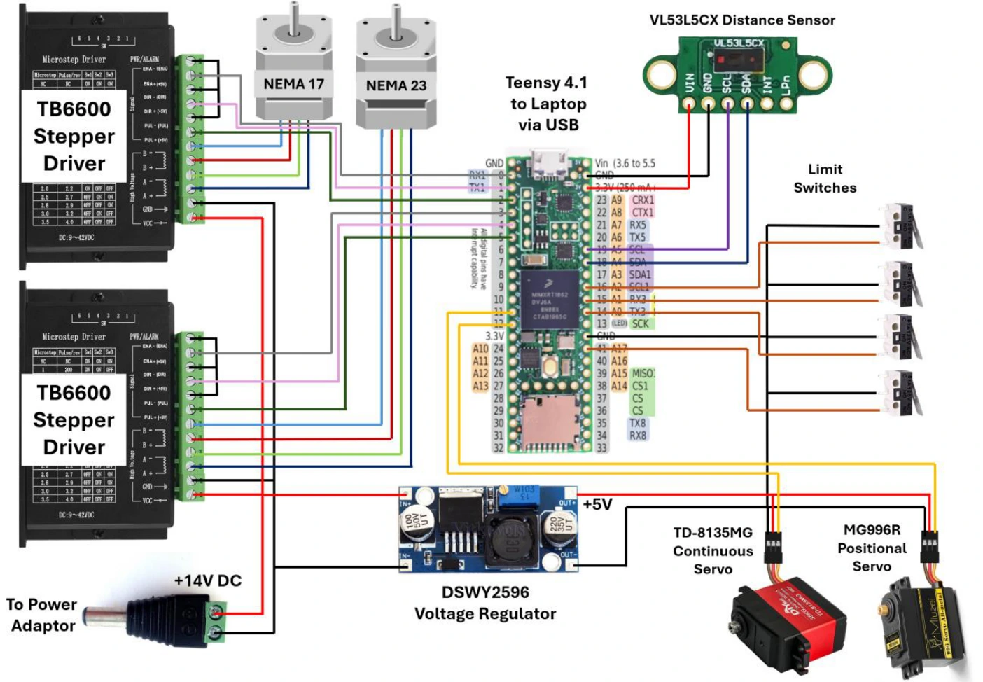
The Teensy 4.1 runs C++ firmware using the Arduino framework and PlatformIO. Two TB6600 drivers control the stepper motors through step and direction signals. PWM drives the continuous-rotation and gripper servos, while four limit switches provide homing references and vertical travel limits.
The power system distributes 14 V to the stepper drivers and steps it down to 5 V for the servos. The Teensy is powered over USB, and the time-of-flight sensor uses 3.3 V and I2C. The team increased the I2C clock to 1 MHz and checked signal integrity with an oscilloscope. The SparkFun sensor library and PJRC PWMServo library provide the device interfaces.
Closed-Loop Height Control
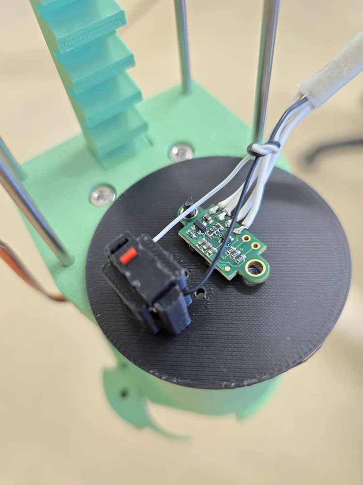
Timed, open-loop vertical motion was unreliable because friction and payload changed the continuous servo's speed. A rotary encoder was tried next, but its approximately 3.77 mm linear resolution was coarser than the roughly 3.45 mm thickness of one poker chip.
The final design uses a VL53L5CX time-of-flight sensor to measure the gap to the top of the chip stack. Running its grid at 4 × 4 instead of 8 × 8 raises the sampling rate from 15 Hz to 60 Hz; the firmware averages the center four zones. A PID loop uses this distance to position the gripper for the requested chip count, even when the initial stack height is unknown. The controller checks that the position error stays within a small threshold for one second before treating the target as reached.
Inverse Kinematics & Smooth Joint Motion
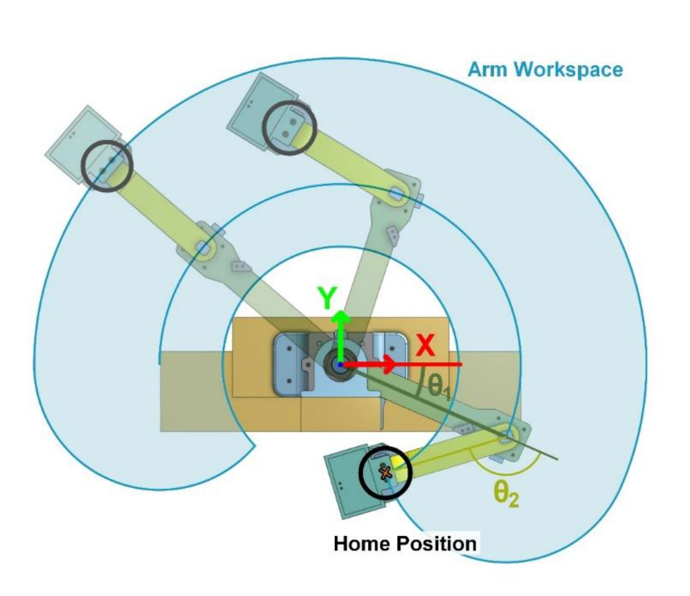
Inverse kinematics converts requested XY positions into the two rotary-joint angles. The firmware checks for unreachable coordinates and invalid joint solutions before beginning a move. Limit-switch homing establishes a repeatable reference for those angles.
Acceleration and deceleration profiles reduce abrupt starts and stops that caused steppers to stall during early tests. With 32-way microstepping, the configured angular increment is 0.05625 degrees; this is the command resolution, not a measured end-effector accuracy. Timestamp-based step generation lets the controller advance the motors without blocking the entire program.
State Machine & Serial Commands
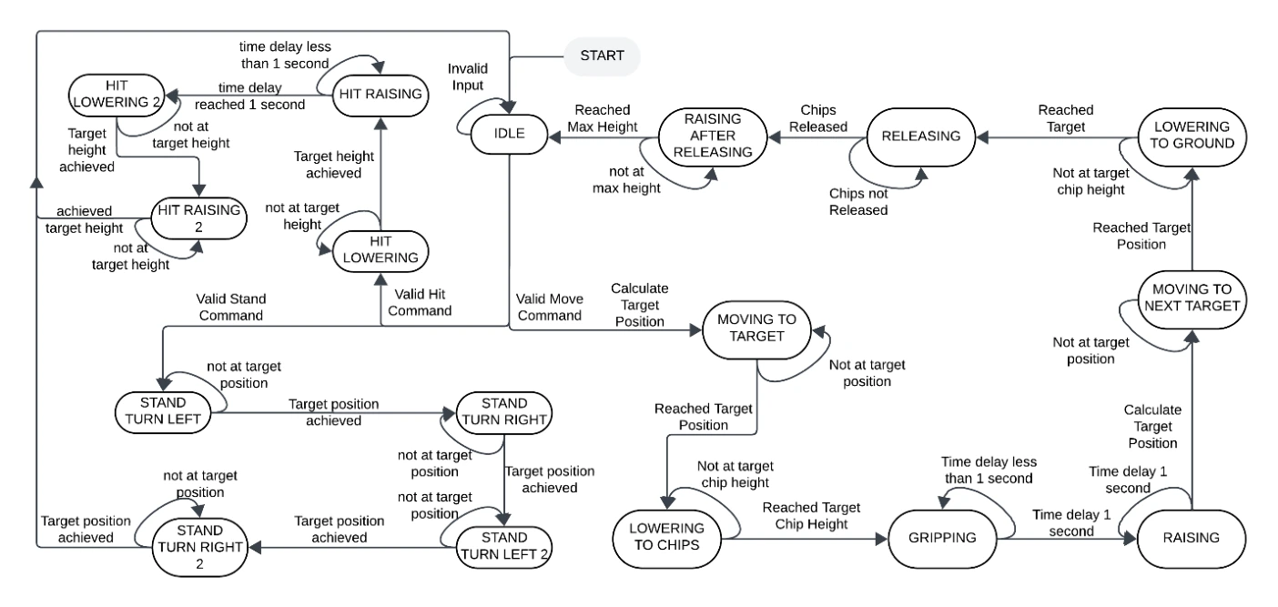
The main state machine sequences moving to the source, lowering, gripping, raising, moving to the destination, releasing, and returning to idle. Separate states implement the hit and stand gestures. Serial input is collected one character at a time between start and end markers, allowing commands to be parsed without waiting for an entire message.
The motion and serial routines are largely non-blocking, while homing and selected gripping delays deliberately block. The firmware is split into configuration, motor-control, serial, and main-loop modules. Debug commands also allow individual joint moves and direct gripper control.
Testing, Limitations & Next Steps
Subsystem tests covered joint positioning, load handling, servo grip strength, sensor calibration, and limit-switch behavior before integrated chip transfers. Physical iterations addressed motor heating, vertical-servo stalling, and occasional missed bottom chips caused by arm sag. The demo shows the integrated manipulation sequence; the report does not provide a statistical pickup-success rate or measured Cartesian positioning accuracy.
The initial Luckfox Pico Max and SC3336 camera setup did not reliably identify cards at the required table-viewing distance, and model-conversion compatibility issues added integration cost. Card vision and automated decision-making were therefore excluded from the final build. Future work could revisit vision with suitable imaging hardware, add obstacle-aware motion planning, and improve the precision needed to place chips onto existing stacks.